Verification: 937b329de42152d7

Friday, May 8, 2020

thread milling inside or outside without special tools

Want to thread mill?
do not got the mill tool?
got a lathe/turning machine?
with a smaller thread turn tool, a boring tool actually.
This tool needs to be a tool for internal lathe, and then we go

as always, show the pic of the tool, this one is from indiamart.com, othervise sandvik
month the tool in you mill chuck and you're on the go


The tool on the pic is the (only) tool you need


we are going to show how to do it in sinutrain 4.7 (4.07) and cycles.
check the video after the instructions..

Chose an internal tool, called ..:


Threading tool is an option in sinutrain, use that, if you do not know sinutrain, check my other videos.

check the video for the rest, ask by mail for everything else


This work inside and outside, cool or what?

/T


Thursday, February 27, 2020

Heidenhain Millplus IT and Tilting the coordinate system in autodesk Fusion 360 CAM with G7

Tilting the coordinate system in Autodesk Fusion 360 CAM with use of G7
Heidenhain iTNC530 should be on the same principle as Cycle 19

In the CAM-system, when you are about to tilt the work plane for 4-5 axis machining, you need to use the right tool-coordinate system to make this work.
I use this rule to tilt the coordinate system:

(Right-hand rule for axis orientation and direction. (R. Hewitt, ManufacturingET.org)

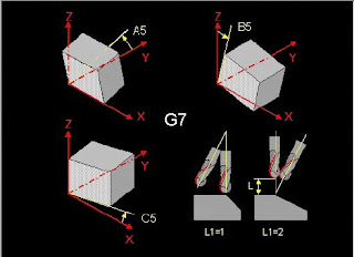
The G7-code in this machine has 3 axis to tilt around  A5, B5 and C5 as X, Y and Z axis, in that order and that make A5 to mill on the Yside, B5 to mill on the Xside and C5 as Zside (damn that's weird..)

(From the millplus IT Ver 5.20 manual)

As mentioned in an earlier post about tilting https://cnccodinguide.blogspot.com/2018/12/millplus-it-dmg-dmu80t-g7.html  the sides have different coordinate systems.
In this case, we will use A5=90, A5=-90 for the Y sides, B5=90 and B5=-90 for the X sides to cover all the sides

All the facts of the CAM in fusion:
Use the pen-shaped button on the upper left.
Find setup1 and setup1 again and the 4 drilling operations but you will not see the tool coordinate system, only the tiny marking for the tool position, Download and use your Fusion 360-program to check this out
We have now a totally 5 coordinate system to juggle with, nice..


The CNC-code:

N1001 (1001)
N10 (T1  D=10 CR=0 TAPER=118deg - drill)
N11 G90
N12 G94
N13 G17
N14 G71
N15 G99 X-10 Y-10 Z-61 I72 J72 K71
N16 G98 X0 Y0 Z-51 I52 J52 K51
N17 G74 Z0 L1
N18 (Drill1)
N19 T1 M6
N20 S5000 M3
N21 G54
N22 G7 A5=0. B5=-90. C5=0. L1=1
N23 M8
N24 G0 X-17.351 Y26.224
N25 G0 Z15
N26 G17
N27 G0
N28 G0 Z5
N29 G81 Z-5 Y5 B1 F1000
N30 G79 X-17.351 Y26.224 Z-1
N31 G0 Z15
N32 G74 Z0 L1
N33 (Drill2)
N34 G7 A5=90. B5=0. C5=0. L1=1
N35 G0 X25.112 Y-14.595
N36 G0 Z15
N37 G0
N38 G0 Z5
N39 G81 Z-5 Y5 B1 F1000
N40 G79 X25.112 Y-14.595 Z-1
N41 G0 Z15
N42 G74 Z0 L1
N43 (Drill3)
N44 G7 A5=0. B5=90. C5=0. L1=1
N45 G0 X17.687 Y24.823
N46 G0 Z67
N47 G0
N48 G0 Z57
N49 G81 Z-5 Y5 B1 F1000
N50 G79 X17.687 Y24.823 Z51
N51 G0 Z67
N52 G74 Z0 L1
N53 (Drill4)
N54 G7 A5=-90. B5=0. C5=0. L1=1
N55 G0 X24.699 Y18.413
N56 G0 Z67
N57 G0
N58 G0 Z57
N59 G81 Z-5 Y5 B1 F1000
N60 G79 X24.699 Y18.413 Z51
N61 G0 Z67
N62 M9
N63 G74 Z0 L1
N64 G7 L1=1
N65 M30
(my G74 needs to be Z-10 to work)

Every G7 has one active value if you'd choose the correct coordinate system when Fusion 360 posts the code.

This video shows how your choice should be done. Take note of how the coordinate arrows are placed on the tool


Back to the CNC-code then. I did a test of the code, it works the way I like it to work. There may be a lot of other ways to do this, I'm not an expert at all, I'm a noob on this, just started.

We will check the video out, I didn't use a proper workpiece ant tool for this, just something as a reference. The height depends of the lack of proper fixture for this type of machining in my DMG DMU80T.
Often, I do not use an edge finder and a bottle of windows cleaner when I'm milling, trust me on that :)


This was not a completely linear description of the solution, but some input on how to do it.
I needed to get this on paper for my own sake, hope anyone else can learn from it.
Comment below if something is wrong, smart, stupid or anything...

AND, PLS, DO NEVER CHOOSE AUTODESK PRODUCTS!

/T

Tuesday, May 14, 2019

Drill/mill on the diametric part of the workpiece in Lathe (tracyl) Siemens 840D sl


Drill on the diametric part of the lathe workpiece(G19)
How it’s done,
Y Rotation (Much more on this later)
Z Distance in longitudinal (standard Lathe Z direction)
X depth (Diameter-dimensions).
Starting codes:
Besides the usual...
SETMS (1.. 4); The number of the driven spindle
TRACYL (50); Choice of machining on the diametric surface and diameter of the workpiece

Y will be the length of the diametric surface in mm or inch. (the rotation)
For example, if you have a diameter of 50mm, work out the perimeter and use these dimensions, 50xPi = 157,07963267948966192313216916398
This represents a whole 360 deg turn, use this for suitable split values between holes.
Example of 4 holes around a 50 detail

N41 SETMS (3) (Enable driven tool, the number may vary)
N42 TRACYL (50) (Enable milling diametric surface, dia 50)
N50 G97 S2000 F100 M3
N60 G0 X55 Y0 Z-20 (starting hole at 0 degrees)
N70 G1 X45 (drilling)
N80 G0 X55
N90 G0 Y 39.269908169872415480783042290994 (90-degree hole)
N100 G1 X45 (drilling)
N110 IS G0 X55
N120 G0 Y 78.539816339744830961566084581988 (180-degree hole)
N130 G1 X45 (drilling)
N140 G0 X55
N150 G0 Y 117.80972450961724644234912687298 (270-degree hole)
N160 G1 X45 (drilling)
N170 ................
SETMS (1) (Switch to the main spindle)
TRAFOOF (return to normal turning)

Sunday, April 7, 2019

Make a PWA-app for windows

There's another way to present your website then the web.
You can use an app format called PWA, Progressive Web App.
All the app content made in the form of a standard webpage, easily changeable.
The app can be made for windows, android, and IOS.
I made a guide on how to make PWA's with Visual Studio (it's free)
The guide shows how to make a windows version app and how to publish the same to Microsoft Store
You'll find it right here
I can even make you the apps for some bucks, ask for that.

Tuesday, March 26, 2019

windows apps for NX CAM, mill and turn

After a long, long interruption, got a heart attack at the new year... (start getting old)

Made windows apps for NX CAM, mill, and turn.
Finally got it to work all the way from Visual Studio to MS Store.
They are on Microsoft store, free and for everything, x86, x64, arm (not Xbox, yet)

For the mill part microsoft store, CCG NX CAM Mill

For the Turn part microsoft store, CCG NX CAM Turn

Try it out and post feedback here, I have not really tested them myself :)

Sunday, December 16, 2018

DMG DMU 80T, how to use

Made a guide for handling the DMG DMU80t Machine.

It's still in its rough state, need a lot of editing

try it, give comments on the error I made.... (none of them done by me ofc... :)

you will find it here https://www.tomasw.com/millplus/

Friday, December 14, 2018

Millplus IT, DMG DMU80T, G7

Change work plane in 4 and 5 axis machines

This is totally new to me, I have to use the machine on and off in a couple of years but never had the energy to take the G7 function to my mind.
It can be a big deal to handle especially on the machine with a rigid table, indexing mill head, and rotating C-axis..
This indexing spindle head can be turned 0 to -90 degrees only.
With the G7 function, you can order the machine to mill/drill of the opposite face of the part where the milling head can not reach. The smart head of the machine knows that it needs to repositioning the C-axis to reach the face automatically, brilliant, I know. Then comes the question, what happens to the zero point, axis and axis directions, and so on.

I will show an easy method to start with the top plane on the workpiece and change to the nearest plane (Right side/ X-) and what happens to the axis and axis directions.


The program
G54 I97
T12 M6 (drill)
S1000 F200 M3
M57 (on our machine, unlock head angle over -31deg)
G0 X10 Y10 Z10 (positions before)
G1 X0 Y0 Z0 (touch the Zeropoint with the tool)
G0 X-100 Z100 (safe position before Indexding the head)
G7 B5=-90 L1=2 (turn the coordinate system to the side of the workpiece)
G0 X10 Y10 Z10 (position before)
G1 X0 Y0 Z0 (touch the same zero on the right side of the workpiece)
G0 X100 Z100 (Go up in X+ and to the right in Z+, Wierd?)
G7 L1=1 (Leave G7, see the late comment down below)
M30

The machine axis, C-axis is the table, not the spindle and I've got no A-axis..


The machine has been programmed to turn the tool from top zero to X- side zero on the edge
It should simulate drilling on the top and the 90 degrees X- side according to the picture


The video will show that  the program will meet the zero point from 0deg and -90deg


As you see on the video, the G7 L1=1 just angle the head to zero and I was ½inch from killing my expensive tool laser unit at the end of the video. Try G7 G5=0 L1=1 instead (or L1=2) for keeping the zero on the tool edge.
Be safe, mistakes cost a lot and the wise man does not know everything.

A picture showing the zero position in -90deg, the corner is the zero point


Charming G-code, no doubt on that.
But the machine make the wierd stuff, When you are in the -90deg, the axis shifts.
You got the Z- axis right in to the workpiece (pic). thats our old (real) X+
Our new X is our old Z, you got X+ for tool up from the table and X- for tool down to the table, Y stays the same.
I've learn from a wise man that if you go from the top of the workpiece to the left/X-side, just tilt the workpiece that way in your mind, then the axis makes sense, tilt your computer to the right and you see it. the workpiece zero points is the same all on the workpiece.


still learning on this.
Is the example hard to understand? yeah, it is and I made this most to understand it myself.
Please leave a comment if you got issues with it, you can help me change the content so it will help anyone who needs the instruction in the best way.

All this made in a Dekel Maho DMU80T

Nice weekend ppl
/T