Blogging about the following awesome things: CNC, CAD/CAM, machining, 3d printing, fanuc 21, siemens sinumerik, siemens 810D, siemens 840D, Siemens 840D sl, Stratasys, Grabcad print, NX, fusion 360, instruction videos, apps
Tuesday, December 8, 2020
NX, right plane (CSYS) from the start, manufacturing
Wednesday, October 14, 2020
Engraving on mantle surface on a round detail Siemens Sinumerik 840D sl
Engraving on the radius surface on a round detail
Prerequisites in
the program is adapted to TRACYL execution:
Check https://cnccodinguide.blogspot.com/2019/05/drillmill-on-diametric-part-of.html
The simulation
program's tool spindle is called 3
The value after
TRACYL is the diameter of the part, in this case, diameter 70
The cycle should
be run in G19 plane
The zero position
of the cycle is changed, e.g. X is the same as Z (depth of milling), then from zero that
sits in the center (differ from the pocket cycles there) X1 is cutting
depth, Y position on the arc, Z is the same as usual
The simulation shows mirrored text, therefore uses mirror writing
Tool "countersink"
Finished program:
Friday, May 8, 2020
thread milling inside or outside without special tools
do not got the mill tool?
got a lathe/turning machine?
with a smaller thread turn tool, a boring tool actually.
This tool needs to be a tool for internal lathe, and then we go
as always, show the pic of the tool, this one is from indiamart.com, othervise sandvik
month the tool in you mill chuck and you're on the go
check the video after the instructions..
Chose an internal tool, called ..:
Thursday, February 27, 2020
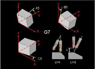
Heidenhain Millplus IT and Tilting the coordinate system in autodesk Fusion 360 CAM with G7
Heidenhain iTNC530 should be on the same principle as Cycle 19
In the CAM-system, when you are about to tilt the work plane for 4-5 axis machining, you need to use the right tool-coordinate system to make this work.
I use this rule to tilt the coordinate system:
In this case, we will use A5=90, A5=-90 for the Y sides, B5=90 and B5=-90 for the X sides to cover all the sides
All the facts of the CAM in fusion:
Use the pen-shaped button on the upper left.
Find setup1 and setup1 again and the 4 drilling operations but you will not see the tool coordinate system, only the tiny marking for the tool position, Download and use your Fusion 360-program to check this out
We have now a totally 5 coordinate system to juggle with, nice..
The CNC-code:
N1001 (1001)
N10 (T1 D=10 CR=0 TAPER=118deg - drill)
N11 G90
N12 G94
N13 G17
N14 G71
N15 G99 X-10 Y-10 Z-61 I72 J72 K71
N16 G98 X0 Y0 Z-51 I52 J52 K51
N17 G74 Z0 L1
N18 (Drill1)
N19 T1 M6
N20 S5000 M3
N21 G54
N22 G7 A5=0. B5=-90. C5=0. L1=1
N23 M8
N24 G0 X-17.351 Y26.224
N25 G0 Z15
N26 G17
N27 G0
N28 G0 Z5
N29 G81 Z-5 Y5 B1 F1000
N30 G79 X-17.351 Y26.224 Z-1
N31 G0 Z15
N32 G74 Z0 L1
N33 (Drill2)
N34 G7 A5=90. B5=0. C5=0. L1=1
N35 G0 X25.112 Y-14.595
N36 G0 Z15
N37 G0
N38 G0 Z5
N39 G81 Z-5 Y5 B1 F1000
N40 G79 X25.112 Y-14.595 Z-1
N41 G0 Z15
N42 G74 Z0 L1
N43 (Drill3)
N44 G7 A5=0. B5=90. C5=0. L1=1
N45 G0 X17.687 Y24.823
N46 G0 Z67
N47 G0
N48 G0 Z57
N49 G81 Z-5 Y5 B1 F1000
N50 G79 X17.687 Y24.823 Z51
N51 G0 Z67
N52 G74 Z0 L1
N53 (Drill4)
N54 G7 A5=-90. B5=0. C5=0. L1=1
N55 G0 X24.699 Y18.413
N56 G0 Z67
N57 G0
N58 G0 Z57
N59 G81 Z-5 Y5 B1 F1000
N60 G79 X24.699 Y18.413 Z51
N61 G0 Z67
N62 M9
N63 G74 Z0 L1
N64 G7 L1=1
N65 M30
Often, I do not use an edge finder and a bottle of windows cleaner when I'm milling, trust me on that :)


