Verification: 937b329de42152d7

Friday, October 1, 2021

Simulating with Millplus IT PC software, nerd level 1000

Simulating with Millplus IT PC-software, WinXP only

=>nerd-level 1000<=


There is a simulation/computer software for the millplus IT v530.

It use to be on the www.millplus.de webpage when it was alive.

It's a freeware without saving capability. Ask, I may give it away.

so for the closest mourners, simulate millplus on a PC

A video of some demo I made few years back:


Use a virtual machine with winxp, install the millplus software.

Without a physical Dongle, no saving is permitted.

Theres possibility to sideload a CNC-program, and simulate it.

You can make your own program in ISO and IPP, but not save.

Use the overlay-file to see the machine-button-command.

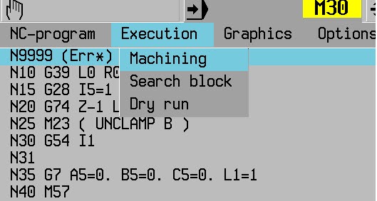
Menu items are in the upper gray field click to open, but the are not clickeble in its own, use arrow keys on the keybord, enter to chose


Startup

You need to run the reference point before anything can be done, by clicking the ”all axis”-button.

Start cycle with CTRL+F8

Now the machine is ready to use.

Place a millplus compatibility CNC-program in the Work-folder, prgnr.pm


Open the program in the same manner you do in the real machine

You may edit and program, but, no saving!


Running a simulation.


When you are in the machining view, chose your program to load it. tap the menu row, and move with arrow-key

You can run the CNC-program here, but the syncron graphic is zoomed out too much to make a good  use, more on this later


Go to the Menu-field, use arrows to go to graphics, point down to wire plot, enter


Now you can start the machining by use CTRL+F8 (CTRL+F7 to stop, F10 to clear)


You need too fix the zoom level if you don’t use G98/G99 after starting the machining the first time.

The scale is out of bounds, use the scale buttons to get a nicer zoom lever, note, Z is still out, havent figure it out yet

The 2nd time you run the machining it will be watchble.

You can use G98 and G99 to make a workpiece and run it in "full 3D" if needed.


Friday, May 21, 2021

Internal keyway in CNC lathe, programming help

 My post on internal key way was removed by blogger (google), check mail at the end

Broaching in CNC-lathe

 The simple way to make an internal slot in your CNC-lathe


You need to get or make the tool, it's not included.

Video: 


An example of tools

Broaching tool


I read a lot of tutorials on how to broach slots, everyone is parametric, with R-values, and so on, and I thought, can you do this easy?.

My solution so far, the main program and a sub-program, some inc programming, and we're there

Main:

N10 G54

N20 

N30 WORKPIECE(,,,"PIPE",256,0,-35,-30,70,30)

N40 T="PLUNGE_CUTTER_3P" ;zero Z at center of tool

N50 G96 S10 M5 ;not the best "no rotation" command

N60 G94 F300 ;feed mm/min

N70 G0 X30 Z2 ;startpos

N80 KILSUB P10  ;subprogram, P=repetition times (how deep you go)

N90 G0 G53 X500 Z600 D0

N100 M30

and the sub:

N10 G54 ;just in case

N20 G91 X0.3 ;inc cut/sub run, aka cutting depth

N30 G90 ;abs prog

N40 G1 Z-20 ;depth in Z

N51 g0 Z2 ;return of tool

N60 m17 ;exit sub

Things that have a deep impact, the P-value is the cutting depth x how many repetitions needed.

something's not completely finished, never tried this for real, just couch-programming


now for the big techs small people bullying:

-------------------------------------------------------------


Hello,


     As you may know, our Community Guidelines 
(https://blogger.com/go/contentpolicy) describe the boundaries for what we 
allow-- and don't allow-- on Blogger. Your post titled "Broaching in 
CNC-lathe" was flagged to us for review. We have determined that it 
violates our guidelines and deleted the post, previously at 
http://cnccodinguide.blogspot.com/2020/12/broaching-in-cnc-lathe.html.

     Why was your blog post deleted?
     Your content has violated our Malware and Viruses policy. Please visit 
our Community Guidelines page linked in this email to learn more.

     We encourage you to review the full content of your blog posts to make 
sure they are in line with our standards as additional violations could 
result in termination of your blog.

     For more information, please review the following resources:

     Terms of Service: https://www.blogger.com/go/terms
     Blogger Community Guidelines: https://blogger.com/go/contentpolicy

     Sincerely,

Tuesday, December 8, 2020

NX, right plane (CSYS) from the start, manufacturing

Get the machine zero secure in NX

a disclaimer may just be in an earlier version of NX, in NX7.5 this is this for real  

NX can be a jerk if you do manufacturing on a workpiece where the CSYS (model zero) are "misplaced"
If you going to avoid that, make the model zero correct for manufacturing from start.
applies for both mill and turn (more on turn below)
check the video


BUT,(maybe an old prob, NX 7.5 do this, can't make it in NX11 now for some reason)
 revolved turning model workpiece work a little different, you should do your model with X as the center axis (usually Z). When you enter manufacturing, like magic, it transforms to Z as it should be....
If you will start with a model with the Z-axis as i "should be" good luck, you got manufacturing with X as center axis, totally wrong and hard to fix at this level. Can do more on that, ask!

Correct me down below if I did a bobo


Wednesday, October 14, 2020

Engraving on mantle surface on a round detail Siemens Sinumerik 840D sl


Engraving on the radius surface on a round detail


Prerequisites in the program is adapted to TRACYL execution:

Check https://cnccodinguide.blogspot.com/2019/05/drillmill-on-diametric-part-of.html

The simulation program's tool spindle is called 3

The value after TRACYL is the diameter of the part, in this case, diameter 70

The cycle should be run in G19 plane

The zero position of the cycle is changed, e.g. X is the same as Z (depth of milling), then from zero that sits in the center (differ from the pocket cycles there) X1 is cutting depth, Y position on the arc, Z is the same as usual

The simulation shows mirrored text, therefore uses mirror writing

Tool "countersink"

Finished program:


The engraving cycle


Friday, May 8, 2020

thread milling inside or outside without special tools

Want to thread mill?
do not got the mill tool?
got a lathe/turning machine?
with a smaller thread turn tool, a boring tool actually.
This tool needs to be a tool for internal lathe, and then we go

as always, show the pic of the tool, this one is from indiamart.com, othervise sandvik
month the tool in you mill chuck and you're on the go


The tool on the pic is the (only) tool you need


we are going to show how to do it in sinutrain 4.7 (4.07) and cycles.
check the video after the instructions..

Chose an internal tool, called ..:


Threading tool is an option in sinutrain, use that, if you do not know sinutrain, check my other videos.

check the video for the rest, ask by mail for everything else


This work inside and outside, cool or what?

/T


Thursday, February 27, 2020

Heidenhain Millplus IT and Tilting the coordinate system in autodesk Fusion 360 CAM with G7

Tilting the coordinate system in Autodesk Fusion 360 CAM with use of G7
Heidenhain iTNC530 should be on the same principle as Cycle 19

In the CAM-system, when you are about to tilt the work plane for 4-5 axis machining, you need to use the right tool-coordinate system to make this work.
I use this rule to tilt the coordinate system:

(Right-hand rule for axis orientation and direction. (R. Hewitt, ManufacturingET.org)

The G7-code in this machine has 3 axis to tilt around  A5, B5 and C5 as X, Y and Z axis, in that order and that make A5 to mill on the Yside, B5 to mill on the Xside and C5 as Zside (damn that's weird..)

(From the millplus IT Ver 5.20 manual)

As mentioned in an earlier post about tilting https://cnccodinguide.blogspot.com/2018/12/millplus-it-dmg-dmu80t-g7.html  the sides have different coordinate systems.
In this case, we will use A5=90, A5=-90 for the Y sides, B5=90 and B5=-90 for the X sides to cover all the sides

All the facts of the CAM in fusion:
Use the pen-shaped button on the upper left.
Find setup1 and setup1 again and the 4 drilling operations but you will not see the tool coordinate system, only the tiny marking for the tool position, Download and use your Fusion 360-program to check this out
We have now a totally 5 coordinate system to juggle with, nice..


The CNC-code:

N1001 (1001)
N10 (T1  D=10 CR=0 TAPER=118deg - drill)
N11 G90
N12 G94
N13 G17
N14 G71
N15 G99 X-10 Y-10 Z-61 I72 J72 K71
N16 G98 X0 Y0 Z-51 I52 J52 K51
N17 G74 Z0 L1
N18 (Drill1)
N19 T1 M6
N20 S5000 M3
N21 G54
N22 G7 A5=0. B5=-90. C5=0. L1=1
N23 M8
N24 G0 X-17.351 Y26.224
N25 G0 Z15
N26 G17
N27 G0
N28 G0 Z5
N29 G81 Z-5 Y5 B1 F1000
N30 G79 X-17.351 Y26.224 Z-1
N31 G0 Z15
N32 G74 Z0 L1
N33 (Drill2)
N34 G7 A5=90. B5=0. C5=0. L1=1
N35 G0 X25.112 Y-14.595
N36 G0 Z15
N37 G0
N38 G0 Z5
N39 G81 Z-5 Y5 B1 F1000
N40 G79 X25.112 Y-14.595 Z-1
N41 G0 Z15
N42 G74 Z0 L1
N43 (Drill3)
N44 G7 A5=0. B5=90. C5=0. L1=1
N45 G0 X17.687 Y24.823
N46 G0 Z67
N47 G0
N48 G0 Z57
N49 G81 Z-5 Y5 B1 F1000
N50 G79 X17.687 Y24.823 Z51
N51 G0 Z67
N52 G74 Z0 L1
N53 (Drill4)
N54 G7 A5=-90. B5=0. C5=0. L1=1
N55 G0 X24.699 Y18.413
N56 G0 Z67
N57 G0
N58 G0 Z57
N59 G81 Z-5 Y5 B1 F1000
N60 G79 X24.699 Y18.413 Z51
N61 G0 Z67
N62 M9
N63 G74 Z0 L1
N64 G7 L1=1
N65 M30
(my G74 needs to be Z-10 to work)

Every G7 has one active value if you'd choose the correct coordinate system when Fusion 360 posts the code.

This video shows how your choice should be done. Take note of how the coordinate arrows are placed on the tool


Back to the CNC-code then. I did a test of the code, it works the way I like it to work. There may be a lot of other ways to do this, I'm not an expert at all, I'm a noob on this, just started.

We will check the video out, I didn't use a proper workpiece ant tool for this, just something as a reference. The height depends of the lack of proper fixture for this type of machining in my DMG DMU80T.
Often, I do not use an edge finder and a bottle of windows cleaner when I'm milling, trust me on that :)


This was not a completely linear description of the solution, but some input on how to do it.
I needed to get this on paper for my own sake, hope anyone else can learn from it.
Comment below if something is wrong, smart, stupid or anything...

AND, PLS, DO NEVER CHOOSE AUTODESK PRODUCTS!

/T

Tuesday, May 14, 2019

Drill/mill on the diametric part of the workpiece in Lathe (tracyl) Siemens 840D sl


Drill on the diametric part of the lathe workpiece(G19)
How it’s done,
Y Rotation (Much more on this later)
Z Distance in longitudinal (standard Lathe Z direction)
X depth (Diameter-dimensions).
Starting codes:
Besides the usual...
SETMS (1.. 4); The number of the driven spindle
TRACYL (50); Choice of machining on the diametric surface and diameter of the workpiece

Y will be the length of the diametric surface in mm or inch. (the rotation)
For example, if you have a diameter of 50mm, work out the perimeter and use these dimensions, 50xPi = 157,07963267948966192313216916398
This represents a whole 360 deg turn, use this for suitable split values between holes.
Example of 4 holes around a 50 detail

N41 SETMS (3) (Enable driven tool, the number may vary)
N42 TRACYL (50) (Enable milling diametric surface, dia 50)
N50 G97 S2000 F100 M3
N60 G0 X55 Y0 Z-20 (starting hole at 0 degrees)
N70 G1 X45 (drilling)
N80 G0 X55
N90 G0 Y 39.269908169872415480783042290994 (90-degree hole)
N100 G1 X45 (drilling)
N110 IS G0 X55
N120 G0 Y 78.539816339744830961566084581988 (180-degree hole)
N130 G1 X45 (drilling)
N140 G0 X55
N150 G0 Y 117.80972450961724644234912687298 (270-degree hole)
N160 G1 X45 (drilling)
N170 ................
SETMS (1) (Switch to the main spindle)
TRAFOOF (return to normal turning)

Sunday, April 7, 2019

Make a PWA-app for windows

There's another way to present your website then the web.
You can use an app format called PWA, Progressive Web App.
All the app content made in the form of a standard webpage, easily changeable.
The app can be made for windows, android, and IOS.
I made a guide on how to make PWA's with Visual Studio (it's free)
The guide shows how to make a windows version app and how to publish the same to Microsoft Store
You'll find it right here
I can even make you the apps for some bucks, ask for that.

Tuesday, March 26, 2019

windows apps for NX CAM, mill and turn

After a long, long interruption, got a heart attack at the new year... (start getting old)

Made windows apps for NX CAM, mill, and turn.
Finally got it to work all the way from Visual Studio to MS Store.
They are on Microsoft store, free and for everything, x86, x64, arm (not Xbox, yet)

For the mill part microsoft store, CCG NX CAM Mill

For the Turn part microsoft store, CCG NX CAM Turn

Try it out and post feedback here, I have not really tested them myself :)

Sunday, December 16, 2018

DMG DMU 80T, how to use

Made a guide for handling the DMG DMU80t Machine.

It's still in its rough state, need a lot of editing

try it, give comments on the error I made.... (none of them done by me ofc... :)

you will find it here https://www.tomasw.com/millplus/

Friday, December 14, 2018

Millplus IT, DMG DMU80T, G7

Change work plane in 4 and 5 axis machines

This is totally new to me, I have to use the machine on and off in a couple of years but never had the energy to take the G7 function to my mind.
It can be a big deal to handle especially on the machine with a rigid table, indexing mill head, and rotating C-axis..
This indexing spindle head can be turned 0 to -90 degrees only.
With the G7 function, you can order the machine to mill/drill of the opposite face of the part where the milling head can not reach. The smart head of the machine knows that it needs to repositioning the C-axis to reach the face automatically, brilliant, I know. Then comes the question, what happens to the zero point, axis and axis directions, and so on.

I will show an easy method to start with the top plane on the workpiece and change to the nearest plane (Right side/ X-) and what happens to the axis and axis directions.


The program
G54 I97
T12 M6 (drill)
S1000 F200 M3
M57 (on our machine, unlock head angle over -31deg)
G0 X10 Y10 Z10 (positions before)
G1 X0 Y0 Z0 (touch the Zeropoint with the tool)
G0 X-100 Z100 (safe position before Indexding the head)
G7 B5=-90 L1=2 (turn the coordinate system to the side of the workpiece)
G0 X10 Y10 Z10 (position before)
G1 X0 Y0 Z0 (touch the same zero on the right side of the workpiece)
G0 X100 Z100 (Go up in X+ and to the right in Z+, Wierd?)
G7 L1=1 (Leave G7, see the late comment down below)
M30

The machine axis, C-axis is the table, not the spindle and I've got no A-axis..


The machine has been programmed to turn the tool from top zero to X- side zero on the edge
It should simulate drilling on the top and the 90 degrees X- side according to the picture


The video will show that  the program will meet the zero point from 0deg and -90deg


As you see on the video, the G7 L1=1 just angle the head to zero and I was ½inch from killing my expensive tool laser unit at the end of the video. Try G7 G5=0 L1=1 instead (or L1=2) for keeping the zero on the tool edge.
Be safe, mistakes cost a lot and the wise man does not know everything.

A picture showing the zero position in -90deg, the corner is the zero point


Charming G-code, no doubt on that.
But the machine make the wierd stuff, When you are in the -90deg, the axis shifts.
You got the Z- axis right in to the workpiece (pic). thats our old (real) X+
Our new X is our old Z, you got X+ for tool up from the table and X- for tool down to the table, Y stays the same.
I've learn from a wise man that if you go from the top of the workpiece to the left/X-side, just tilt the workpiece that way in your mind, then the axis makes sense, tilt your computer to the right and you see it. the workpiece zero points is the same all on the workpiece.


still learning on this.
Is the example hard to understand? yeah, it is and I made this most to understand it myself.
Please leave a comment if you got issues with it, you can help me change the content so it will help anyone who needs the instruction in the best way.

All this made in a Dekel Maho DMU80T

Nice weekend ppl
/T

Friday, December 7, 2018

Nice pocket mill, DMG DMU 80T

The only thing this week, I did some milling in the DMU80T
Programmed in the Millplus IT v520 in IPP mode (mostly)
Made a video of it :)
The sound is 10 seconds to late, doesn't matter much, it's a cool video.
Check me out, laid back, drinking coffee in right on the video at 0.28-ish, no stress there at all.
Spindle speed 5000 rpm (S5000)
Table Feed is 1000 mm/min (the metric stuff, fast as...) You inch guy, count to get the real feed.. one inch is 25.4 mm (got to be 39.3 inch a minute? (inch/min?) )
I think the feed is to high, but it works on a single piece...
Oooh forgot, I use a 10 mm cabide endmill, the workpiece is in brass.


Have a nice weekend :)
/T


Monday, November 19, 2018

NX turning, NX 7.5 CAD/CAM and later, whole course, for free

NX Turning, Manufacturing in NX

Made a website for the Turning part of Siemens NX training.
It's the same as the mill part but adapted for turning parts and includes threading, there are also some video instructions attached to this instruction that will explain the work thoroughly.
It shows file management, sketching, model (Solid modeling), tool handling, and manufacturing.
It's free to use.
It fits (most parts/tested in) NX6, NX7.5, and NX11

You will find it at https://www.tomasw.com/nxturning/nxturning.html

Made it from some weird conversion site, word to HTML, it may be funny in some parts.

Made a new apps for android.

These apps are the same as the mill and turning training material made for NX n an easy to use format,
You will find the mill app right here
You will find the turning app here

please comment the above, need feedback so I can make those resources better and more useful.

/T

Tuesday, November 13, 2018

NX 7.5, converting units, inch to mm, mm to inch

If you got a model from internet, www.grabcad.com 's library or from some other source, you may end up with the "wrong" units on your model.
In NX 7.5 there is no drop down menu to make a unit conversion between metric and imperial units.
But there is a way anyway. In NX they did add hundreds (?) of DOS-programs that works like drop down menu command, but they did not added them the drop down menu object in the NX program.
If you'r familar to the CMD-command promt, go to the picture, otherwise follow the instruction.

Go to Search in windows, You got it down by the windows logo (start menu)
Write CMD in the search, click the Command promt that appear.
Now write C:\program files\nx 7.5\ugii\ C:\cadcam\model.prt -mm and enter
the "C:\cadcam\model.prt" should be you own part name and folder and "-mm" the conversion you want to preform I assume that you use -inch if you'r going that way, but I'v never tested this.
see the example down below
I'm sorry for the "too big" image, but it's hard to see othervise, I hope that this doesn't kill the layout on your mobile unit

NX 7.5 CAD/CAM and later, whole course, for free

I'v have a week with a basic NX 11 CAD/CAM course, the newbie one.
So when my student are doing their training on theres computers, I got some free time for my own work.
I created my training instruction as an online version, just for you(!!!). with both CAD and CAM, it's the one I use when I educate in CAD and CAM
It's a well-utilized time. (?)
Because I am a bit lazy I used Words translating tool to translate, so the language can be somewhat rough, please comment on things I missed and things that wrong linguistically.
It fits NX7.5, but most of the content fits even NX11
Use it for free even for professional use (It can't be wrong to paypal some $ if you use it to make money for yourself)
Do link my blog or webpage.

I hope that you find it useful
==>NX Milling instructions<==

More of the same will come later, NX turning, fanuc basic course, siemens 840D basic course, Millplus IT basic system. just wait :)

Friday, October 26, 2018

just videos, the week...

This week, lot of progress


For my students, they learn a lot.

Check out his weeks videos:


My own pleasure:


Make a comment or a complaint, ("-do not do it that way" and so on....)
We can take a discusion about everything, I'v got close to 35yrs in this, I know a lot, but not everyting so your comment can make.. me to relearn? (or not :)

have a nice weekend ppl !!!!

/T


Friday, October 19, 2018

made a *caugh... caugh* small error

Can happen to every one!

Yehaaw, made it, in front of my students...

I do not think it's a problem, misses in CNC programs and manual manufacturing happens all the time, just wait. it's this that makes a good CNC programmer/manufacturer, try hard to do, try and .... fail... the first time, but then, finally, on the mark on every take....it makes a good and thoughtful programmer, as a mcahine'/workshop owner you need to let this s..t happen, it makes you worker better to earn your profit...
I know, 30+ years in single part machining, I done this, not every day but close.
Nothing can protect you of this (If you not have exeptional clever or lying or lazy personal)

Don't kill your machines to much and do not abuse to much cutting tools, you'll be fine :)
It is part of the development of a future expert
video:


BTW, be carefull!! (closed doors, all security locks on its place)

Tuesday, October 16, 2018

cheap action cam, worth it?

Bought a cheap 1080p action cam

Are those any god? the Gopro5 I was using was "murderd" by some one, the case is broke, can't be fixed according to Gopro, they don't repair their cams. You need to buy a new one.
The Gopro has done a good job with good results.

Did'nt use action cams much so $400 for a new one, not a chance..
Bought a $30 cam instead.
Did edit it in 720, din't made anything much different
Check the video from the $30 cam


I don't have a good Gopro video from the 5 version to show, but we did a video with the gopro4.
Watch it and see if there are any differents..


I know that the cheap cam has no good close up/macro function and I did go close when filming
But for $30?
farly good I think
The actioncam got wifi and a pretty good app.
What cam then? it's a Rollei actioncam 372.
I'll try it more and present the results later

It's later: the water resistance plastic case has no chemical resistance what so ever, using it with cooling fluids make the plastic to crack and it falls apart, useless

/T

Sunday, September 30, 2018

Milling in lathe, siemens sinumerik 840D

If you got driven tools in your lathe, try this
Mill in the lathe, on the edge of the workpiece.

milling in lathe
If you can't see the moving gif, check my youtube

Raw code with comments:

N10 G54
N20 WORKPIECE(,,,"CYLINDER",0,0,-100,-80,200)
N30 G0 G53 X400 Z600 D0 (safe position, tool change)
N40 T="FRÄS10"
N50 M6
N60 G94 F100
N70 SPOS[1]=0 (set chuck (workpiece) to 0 degrees, need to be before SETMS(1) )
N80 SETMS(1) (set work spindle, driven tool)
N90 S1000 M3
N100 TRANSMIT (start G17, end plane milling)
N110 G0 X70 Y35 Z3
N120 Z-3
N130 G1 Y-35
N140 G1 X-70 (value X2 without DIAMOF, program in dia)
N150 G1 Y35
N160 G1 X70
N170 G0 Z5
N180 G0 G53 X400 Z600 D0
N 85 TRAFOOF (return to turning, G18)
N190 M30


How do you do that?
The programming make you able to do a mill program on the edge, see the pictures below.
If you does'nt use DIAMOF (and don't) the X-coordinate will be programmed in the double value, the machine (lathe) use diameter measurment on X.. If you use DIAMOF do'nt forget to DIAMON after the milling, otherwise everything will be interesting when you try to do your ordinary turning afterwards
And don't forget to shut off the milling with TRAFOOF (yep, correct spelling)

Programming, the blue square is the milling in the example, Zero on X and Y is in the middle, Z- is down into the picture

Make a comment if you want a more detailed explanation! :)

/T


Thursday, September 27, 2018

New android app

Made it again

I made an new app for android without certain public interest.
I thought, " I want to make a new app, no idea what type, but I want to make one"
And then it hits me like a flash
I shall make an app that shows this blog in a little window on an android thingy

This app is not truly useless, you can use this blog much easier with the app, just open the app and read this fabulous blog.

You can thank me at any time :)

So where do i find this app?
Go to Google play <-link

The apps name is CNC Coding Guide Blog and is a free blog reader app with this blog in aim.
However, I'v got a small problem with it.
I can't test it before publishing, lost my android phone, or my daughter did, it is somewhere in the house, so it is up to you to try it out and tell me if it's a hit or a miss.

Have a nice one
/T